A hydraulic schematic shows function and connections rather than physical layout. Read it by tracing energy and flow paths through operating states, then connect each symbol to the actual component model.
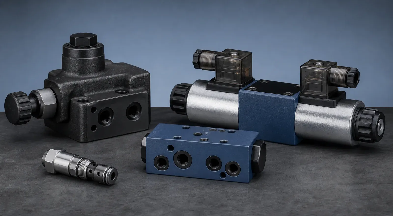
Turn a circuit reference into a component RFQ.: Send the schematic, component tag, complete model code, machine function and photos so the required pump, motor or valve can be reviewed.
Start with the power path
- Locate the reservoir, suction line, prime mover and hydraulic pump
- Identify the main pressure line, relief path and pressure measurement points
- Trace the return line through filters, coolers and the reservoir
- Note separate case-drain, pilot and load-sense lines
Read the control states
- Directional valve boxes represent available spool positions
- The normal position is determined by springs, detents and actuators
- Pressure valves respond to pressure at their pilot connection
- Flow-control symbols show restriction, compensation and check-valve bypass paths
- Dashed lines usually indicate pilot, control or drain connections
Use the diagram for replacement sourcing
- Confirm component function before searching by appearance
- Pair each schematic tag with its complete model code and nameplate
- Record pressure, flow, displacement, voltage and operating state
- Compare mounting, ports and external pilot or drain requirements
- Treat any unresolved symbol or connection as an open compatibility point
Symbols you will see in most circuits
| Symbol group | What it tells you | What to verify on the machine |
|---|---|---|
| Pump and motor circles | Fixed or variable displacement and flow direction | Model code, rotation, mounting and shaft data |
| Directional valve boxes | Number of positions and the flow paths in each | Spool symbol, voltage, connector and manual override |
| Pressure-control symbols | Relief, reducing, sequence or unloading function | Set pressure, pilot source and adjustment location |
| Line types | Main flow, pilot/control, drain and enclosure boundaries | Actual port labels and external pilot or drain plumbing |
| Reservoir, filter, cooler and accumulator | Support functions and cleanliness path | Element rating, accumulator gas precharge and connections |
A repeatable reading order
- Identify every major component tag and its manufacturer reference
- Trace the neutral or de-energized state first
- Trace each energized or shifted state and note which components move
- List every pressure, flow, pilot and drain connection the component needs
- Compare the schematic claim against the nameplate and installed plumbing
- Keep the circuit tag alongside the RFQ so each item stays traceable